The Dirty Truth about USB device Charging
How many devices do you have that charge over USB? How many devices require you to do something special, or have a special adapter to do it?
The last few cell phones I’ve had have USB micro or mini ports to charge from. I figure I can take a USB A Male to USB micro/mini Male cable and just plug it into a USB port and get power… except that doesn’t work some times. Then there are the Apple devices. You’ve got your iPods, iPhones and iPads. They do their own thing as well. What’s a geek to do?
Well, the Chinese started mandating a specific configuration for cell phone charging via USB (shorting DATA- and DATA+ pins together) back in 2007. The EU got the big cell phone manufacturers onboard in 2009, with the US wireless industry coming along also. The bad news is that the EU standard doesn’t have to be implemented until 2012.
So that problem is resolved, right? That’s just cell phones. Others will probably jump on the band wagon, but there will be hold outs. So, how do you design a USB charger in the mean time? The Chinese standard is here, but that leaves our device non-apple compliant. We don’t want to miss out on the apple market do we? I hear you say, “but that means another product, and that’s expensive.” We’ve got a handy generic circuit to allow you to use the same design for both charging standards by just replacing a couple resistors. First, let’s look at the standards.
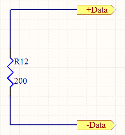
I don’t have the Chinese standard, but all articles agree that it is just shorting the D+ and D- lines together. Easy enough. Now, the Europeans did their own thing… sort of… not really. They supported the USB Battery Charging Specification, which instead of shorting D+ to D-, puts a 200 Ohm resistor between them. It’s practically the same thing. So we can meet those two standards with a 200 Ohm resistor, or if you really want to short it out, a zero Ohm resistor.
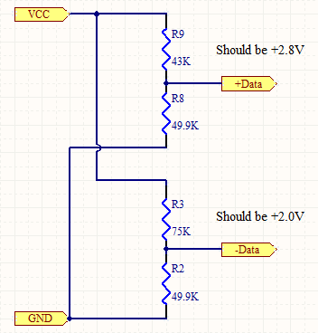
Now onto Apple’s USB charging setup. Luckily, there are intrepid explorers who did the hard work there. There’s two Apple USB charging circuits, low and high current. To change between the two we just need to switch out the resistors. Here’s the circuit for the high current resistors.
Now, we just need to combine the two. Merging the two circuits we get:
Now realize, that installing all five resistors will not meet either of the charging standards. However, if we install R2, R3, R8 & R9, we will have an Apple format charging port. If we install just R6, we will have an EU standard charging port. If we replace R6 with a zero Ohm resistor and leave the other resistors off, we will have a Chinese standard charging port.
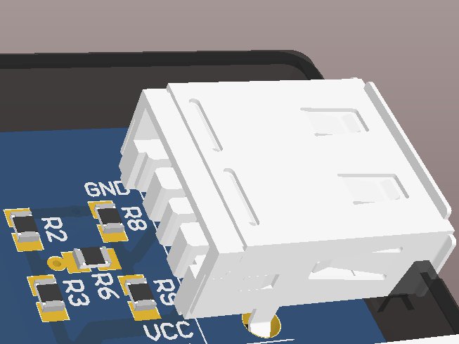
Now, instead of two different boards, we can use the same board with two or three assembly variants to support different devices. First, here’s the layout for the resistors connected to a USB A Female board mount connector:
The circuit requires two layers if using surface mount components.Blue is the bottom layer and red is the top layer. If using thru-hole, traces could be ran under the resistors. The resistor layouts shown are for 0805 resistors. They can be smaller, since they dissipate very little power (less than 1/8 W). The same can be said for the traces. I had the room, so I chose 0805s with larger traces. Make sure to keep your GND and VCC traces large to support the current on them. Here’s the 3D view of the layout:
And there you have it, one circuit and layout for multiple USB charging standards. Enjoy!
-
[…] +5 VDC – This guy gets a lot of connectors. He has the Powerpoles, terminal block and USB ports with places for the resistors necessary for the different charging standards. See my prior post about USB charging. […]
[…] charging is an unreasonably complex subject. You can read lots about the details here and here and here (and of course here), but I’ll […]
[…] on USB charging, I discovered lots of pinouts, technical data, and user workarounds. For example, The Dirty Truth about USB device Charging discusses adding resistors for charging cellphones, but that's not what I need for the Zen Plus. […]
[…] initial searching found reference to shorting out the data pins on the charger or placing a 200 ohm resistor across the pins I completed this mod to a couple of my chargers and great one started working correctly the other […]
[…] USB charging port of smartphones, tablets and the like often use coded USB ports. The charger has a defined set of resistors connected between the USB pins. The device detects the code and knows that it can draw more than the standard 500mA from the charger via thsi SUB cable. See this article. […]
[…] Charging; blog.curioussystem.com; wayback machine dated 01 December 2010; printed 14 May 2015; http://blog.curioussystem.com/2010/08/the-dirty-truth-about-usb-device-charging/; pp. 1-6 […]
[…] +5 VDC – This guy gets a lot of connectors. He has the Powerpoles, terminal block and USB ports with places for the resistors necessary for the different charging standards. See my prior post about USB charging. […]
Leave a Comment


You don’t need the 2nd set of voltage divider as your 200 ohms resistor would past the same +2.8V to the other data line.
So your 5 resistors solution has became a 3 resistors one.
Joe,
You never have all five resistors populated at the same time. Installing the 200 ohm resistor into the Apple charging circuit would screw up the voltages presented on the data pins and then it may not be recognized as a valid charger.
Only 3 resistors needed, delete R3 and R8
EU charger: R9=no fit, R6=200R, R2=no fit
Apple charger: R9=100K, R6=20K, R2=100K
(gives 2.72V and 2.27V and works perfectly)
Do you know of anywhere that sells one of these?
Thanks for you article, i have build a 1,5A charger, powered by 5-40VDC for charging on the go 🙂 it works pretty well an loads my mobile in just under one hour because of your info 🙂
I’m glad that it proved useful for you.
“which instead of shorting D+ to D-, puts a 200 Ohm resistor between them”
Actually the USB charging spec says a resistance of *less than* 200 ohms, so a direct short is still compatible with the USB charging spec.
How much watts does the resistor has to handle?
The resistors have very little current running through them. You can use a 1/8 W rated resistor for the 200 ohm resistor. You can probably get away with less, but I don’t know what other resistors are in the end device.
In your Apple high current image you have D- and D+ labelled the wrong way around. If you refer back to this article you will see this:
http://learn.adafruit.com/minty-boost/icharging
Using the 3-resistor layout suggested by tony (and others), what if you had 550, 200, and 500 Ohms? That’s a voltage divider that gives you 2.8v on D+ and 2.0V on D-, and also has 200 Ohms between the two. At a total of 1250 Ohms, at 5V, that draws 4mA, which isn’t too bad.
With a little more effort, you could put a DPST switch to disconnect the Vcc and Gnd feeds to the voltage divider, and a LED off of the Vcc feed to indicate that it’s in “Apple” mode.
Note: above idea needs testing. YMMV
My Samsung Galaxy Note 10.1 has slightly different layout
10 K Ohm to +5 rail
3 K Ohm to ground rail
+d and -d connected to the junction.
Only way I could get the stupid thing to go to full charge mode
I am curious if this will work on ios 6 and ios 7.
I have 2 uses for this: 1) a component video cable that is “not supported” that I would like to modify.
2) I have previously modified a belkin car charger to support line out; all that was required was the addition of a 1M resistor i believe. I have hardwired this to a 12v source in my car and the cord works as it should for ipod/line out audio, however my iphone will not charge with this cord and I would really like to fix this.
We have Samsung Tab3 10.1. We have a custom USB controller that we are trying to communicate with, while charging at greater that +500mA (Quick240.com). We have yet to get this to work. I have a call in to Samsung to see if there is a work around.
We also verified that the following will cause the table to charge as well:
10 K Ohm to USB +5V
3 K Ohm to USB ground
+d and -d connected to the resistor network junction.
This also worked:
250 K Ohm to USB +5V
75 K Ohm to USB ground
+d and -d connected to the resistor network junction.
But connecting
500 K Ohm to USB +5V
150 K Ohm to USB ground
to each d+ and d- (four resistors, two networks) but leaving d+ and d- not connected didn’t work.
Also, using the first configuration, if you short and unshort d+ and d- the tablet will go into and out of drawing full current.
Just to clear something up: the USB battery charging specification actually specifies the resistance between D+ and D- to be up to 200 Ohm. So the ‘European’ and Chinese standard are actually pretty much in agreement. Ay sight on Apple coming to agree to this standard by now?
Chad, is it possible the polarity of the connections to the voltage divider is reversed? In your diagrams the 2.8V connection goes to +Data while in https://learn.adafruit.com/minty-boost/icharging it goes to the the D- connection. Or maybe my brain is confused from peering at the screen all day.
—
Joe
good article but your images are broken
Nothing like cleaning up links on Memorial Day…
I can confirm the 100k from + ve and 100k from -ve to the D+ and D- with a 22k resistor between +D and -D works perfectly with the iPhone 6 and a new iPhone SE.
The iPhones charge as they do on the standard iPhone 5v 1a charger.
Keith.
To convert the popular synchronous converters into a more universal Apple charger for all types of gadgets as part of a smart home with DC power in the well-known scheme, you should replace the 43 kΩ resistor with a 39 kΩ resistor to obtain a current of 2A in devices that need it.