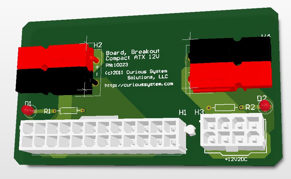
Compact Emergency 12V DC Power Supply
This board was designed to be a good beginning board for someone to learn to solder on. There are a lot of amateur radio operators that originally got into the hobby as part of an emergency communications group (RACES, ARES, etc.). This board is designed to start them down the path to the… hardware side (cue evil laugh).
With only four connectors, two resistors and two LEDs, this gives a good variety of things for people to try their hand at. This design improves on my prior ATX 12VDC only design by using fewer connectors and protecting them better. This was done after it was realized that the PCB contacts for the Anderson PowerPole connectors are not that rigid. I also realized that in an emergency situation, people will not need that many 12VDC rails to use. This design will give two 12VDC rails that will, depending on the power supply they are hooked to, put out 11 to 19 amps on each rail. There are LEDs across each rail to let the user know if it is powered.
The finished board is designed to be thrown in a “go bag” so that one can quickly convert an unused PC into a 12VDC power supply in the event that the primary supply has met its maker, or there are simply not enough amps to go around. Since PCs are pretty much everywhere these days, being able to convert one to a power supply seemed like a good thing. To improve on the robustness of the board, the PowerPole connectors were recessed so that they do not hang over the edge of the PCB. It is further advised that they are tacked down with hot-melt glue to help keep them in place, and to make soldering them easier.
Along the lines of this being an introduction to soldering, I skimped a bit on the copper layers. Normally I like filling the extra space with ground or DC voltage copper pours, to make sure there is as little resistance created and to dissipate heat. That last one can be a bit of a problem to someone new to soldering. It will take someone quite a while to heat up large copper pours enough to get a good solder joint. While there is still more than enough copper on the board to support the maximum current, it makes soldering a little easier. Another tip on making soldering easier, use small dabs of hot-melt glue to secure the connector to the board so that you don’t drop it before you get it soldered. Don’t put the glue on the leads, but on the body some where. That’s my tips for soldering the board. So, without further adieu, here are the gerbers and the parts list:
| P/N: 10023 | ||||
| Description | Designator | Manufacturer | P/N | Qty. |
| ATX v2.0 Motherboard Header | H1 | Molex | 442060007 | 1 |
| ATX 12V EPS Header | H3 | Molex | 39-28-1083 | 1 |
| 2×1 Powerpole Assembly | H2, H4 | Anderson Power Products | 1377G12 | 4 |
| 2×1 Powerpole Assembly | H2, H4 | Anderson Power Products | 1327G6 | 2 |
| 2×1 Powerpole Assembly | H2, H4 | Anderson Power Products | 1327 | 2 |
| LED | D1, D2 | Knightbright | WP132XID | 2 |
| LED Resistors, 1 kΩ, 1/4W | R1, R2 | Various | Various | 2 |
-
[…] « Compact Emergency 12V DC Power Supply […]
[…] affiliated with had a get together with good food, friends and activity. We soldered together the Compact ATX 12V board that we wrote up a little while back. There were a few people who were unable to stay and put it […]
Leave a Reply to ryan brooks Cancel reply


Could you share your molex footprint for the power supply connector (H1)? It seems like you’ve got it nailed.
Or any tips on making footprints, I always struggle with this in Altium. Thanks!