Debug adapter for eZ430
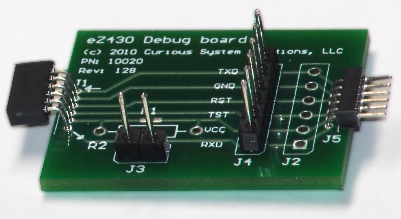
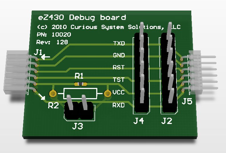
For those of you who do prototyping with the eZ430 or eZ430-RF boards, this may be of interest. It’s a debug adapter that you can put inline to make use of a logic analyzer or other test equipment easier. It expands out to 0.1″ spacing posts from the 0.05″ spacing used in the eZ430 connectors. It also has room for either a SMT or thru-hole power resistor and a header to measure current on the VCC line. J2 and J5 are designed to be mutually exclusive. The Mill-max headers (J1 & J5) are not cheap so the board is designed to take a 0.1″ spacing header if you make your own boards, to save money. J2 can be either vertical (as shown) or a 90 angle. It’s your choice. Arrows were also put onto the silk screen layer so that you know which way the signals are going on the TX and RX lines for the eZ430-RF.

eZ430 debug adapter with 50 mil pitch connector
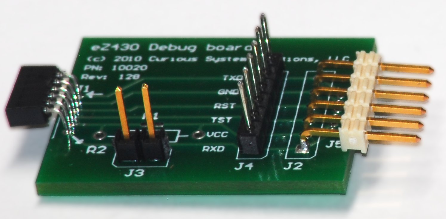
We try to make the board as flexible as possible so that you don’t have to fab several boards, since boards cost money. You can see above and below the two varieties of the board (50 mil and 100 mil connectors).

eZ430 debug board with 100 mil connector
Anyhow, here are the gerbers. Here’s the schematics. and the BoM:
| Designator | Description | Manufacturer | Part Number | Qty |
| J1 | 0.05” Pitch Right Angle Socket | Mill-Max | 851-43-006-20-001000 | 1 |
| J5 | 0.05” Pitch Right Angle Plug | Mill-Max | 850-43-006-20-001000 | 1 |
| J2, J4 | 0.1” Vertical Header Strip, 6 Position | Various | Various | 2 |
| J3 | 0.1” Vertical Header Strip, 2 Position | Various | Various | 1 |
| R1 | SMT current monitoring Resitor | Various | Various | 1 |
| R2 | Thru-hole current monitoring resistor | Various | Various | 1 |
Please remember that either R1 or R2 must be installed, or J3 must be shorted for the attached device to work. Otherwise you will have an open on the VCC line. Enjoy.


