Directions for Soldering of Compact Emergency ATX 12V Output Board
Last Friday night one of the local amateur radio groups that I’m affiliated with had a get together with good food, friends and activity. We soldered together the Compact ATX 12V board that we wrote up a little while back. There were a few people who were unable to stay and put it together. For them (and for anyone else trying this), I have put together some instructions on how to put it together.
Equipment Needed – The Appetizer
To start, here are the tools that are needed for the project:
- Soldering Iron
- Solder
- small set of diagonal cutting pliers/dikes
- hot melt glue gun
- hot melt glue
Please make sure you solder in a well ventilated area like an open garage. Inhaling enough fumes will give you a headache and can cause long term problems with repeated exposure.
Soldering Parts – The Main Course
Depending on your soldering ability, you may also want a desoldering iron it help fix any incidents you may have. A good guide to soldering is located here. Please look at its explanation of a good/bad solder joint. The most common problem during the soldering of these were solder joints that didn’t join.
All parts are mounted on the side of the PCB that has the text on it. They are soldered from the reverse side. We suggest soldering the parts in a particular order, mainly to make sure we have room to work. One suggestion we have is that if the connectors are moving around on you, use a dab of hot melt glue to secure their housing to the PCB. Do not use the hot melt glue to hold the leads because they will get hot enough to melt the glue. Another tip is to prop up the PCB so that it is level. This will help your connectors to mount flush with the board and not have a cant to them.
Since many people making this kit do not solder day in and day out, we suggest starting with the Anderson PowerPoles. Next are the resistors and LEDs, followed by the two ATX power connectors. For easy reference the order is:
- PowerPoles (H2, H4)
- Resistors (R1, R2)
- LEDs (D1, D2)
- Power Supply Connectors (H1, H3)
PowerPoles
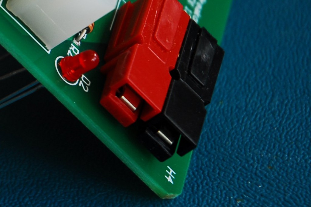
Starting with the PowerPoles, we need to put the contacts into the housings and mate the housings. The contacts are oriented so that they “click” into position. A good amount of force is required to insert them. It is recommended that, once the contact is oriented in the housing, a table or other hard, immobile surface is used to push the contact in. After the contacts are in, mate the red and black housings together by sliding them together. The figure below shows the correct orientation of the contact and housing on the board.
Please make sure that you have the polarity correct when you solder in the PowerPoles. There are plus and minus signs on the PCB to help with installing these. The red side goes on the “+” side and the black portion goes over the “-” side.
Resistors
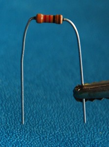
Resistors are nice because they are not polarized, and can be put in either direction. The easiest way to insert them is to bend the leads first, as shown below.
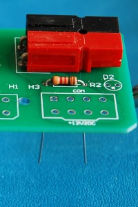
After bending the leads, insert both into the appropriate holes and pull through until the resistor body is snug with the board, like so:
LEDs
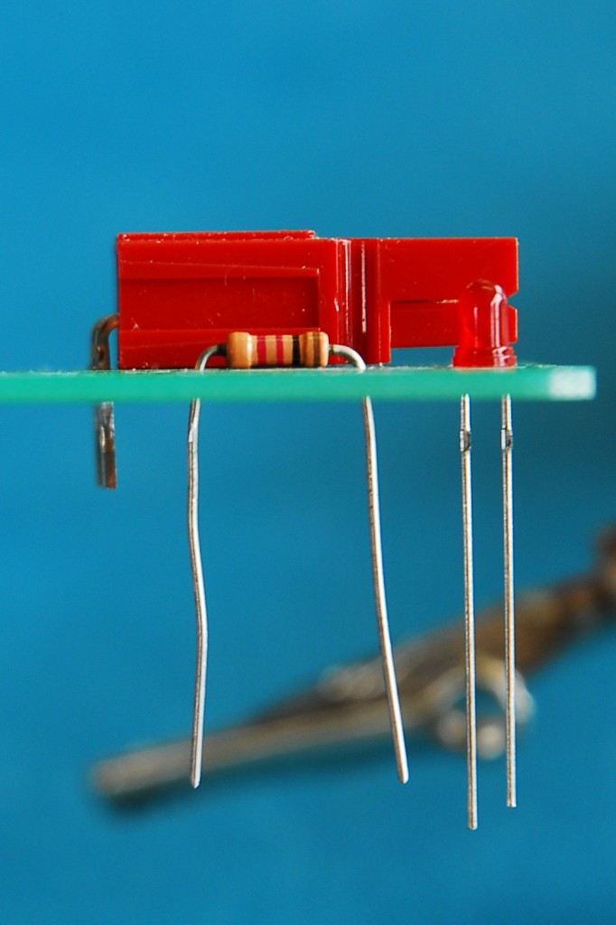
LEDs are polarized, so you do need to watch how they are mounted. The polarization of an thru-hole LED (what we are using) is determined by the lead length. The shorter lead is the cathode and matches the bar on the LED symbol. See the wikipedia entry for more information. For this project, the short lead of the LED must be mounted to the outside of the board. The following figures show the LEDs inserted correctly.
ATX Connectors
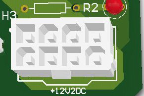
The 24-pin ATX main connector (H1) only fits into the board one way, if you purchased one with the retention clip(s). The part number listed in the original article has one retention clip. The secondary ATX connector (H3) is aligned so that the connector retention clip matches the bump in the connector outline on the board.
The question was asked if all the pins need to be soldered. For H3 they all do. For H1, only some do, but it will be easier to just solder them all than worry about soldering the correct ones. The ones that are not used will solder very quickly and provide mechanical support to the connector, as some force is occasionally needed to remove the connector. When soldering in H1 & H3, start by soldering pins in opposite corners of the board this will attach the connector and then you don’t have to worry about the connector pulling away from the PCB as you solder it. Make sure you get good solder contact. It doesn’t take tons of solder, but you do need to be patient enough to see the solder wick into the pin hole.
How was the Meal? – Board Testing
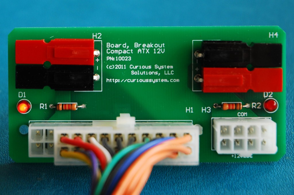
After all the components are soldered on, but before trimming the leads and insulating the leads with glue, we test the board. The first test is connecting the main ATX header to H1.
What is that you say, why are there fewer pins on the connector? Early ATX power supplies only had a 20-pin connector. The spec later increased that to 24 pins. It is backwards compatible and will only insert one way. Next we test the other connector. Remember to leave H1 plugged in because it turns on the power supply.
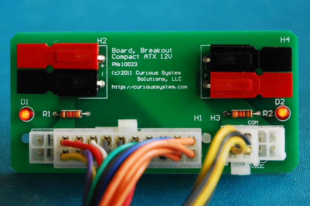
Again, what’s with the missing pins. As time progressed, computers needed more power and so additional pins were added to the auxiliary 12V connector. And yes, this one is backwards compatible too and will only allow the 4-pin connector to plug in one way.
Wrapping it up – Desert
Trimming the Leads
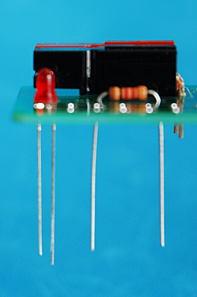
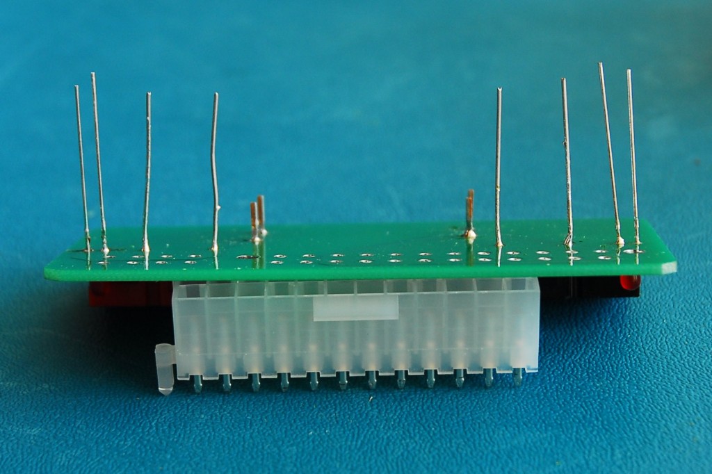
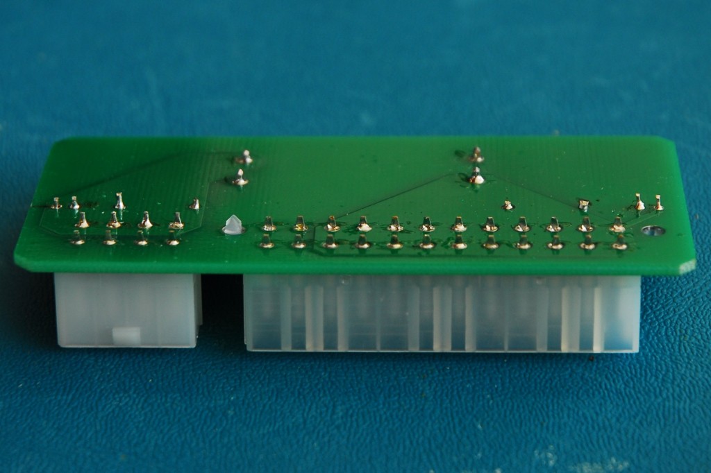
After all the parts are soldered, the leads need to be trimmed so that the board can lie flat and a minimal amount of glue is used to protect the leads from shorting. All leads are trimmed to the lead length of H1 & H3, the ATX connectors. The following figures show the board before and after lead trimming:
Protecting the Leads… and Things Stored with it
If you are using this in a pinch, you really don’t want to have to worry about accidental shorts and their collateral effects. To solve this we coat the leads with hot melt glue. This also gives us the added benefit of getting rid of lots of small, sharp, pointy metal objects. If you keep this on a surface you may scratch it without protection. If you keep it in your go bag, you may scratch everything in the bag and rip the bag as well.
If you’re not sure about the hot melt glue another option is using funky foam from a craft store. Take a thick sheet of the funky foam and cut a piece out that is a little bigger than the board size. Next adhere it to the bottom of the PCB using liquid electrical tape or another non-conductive adhesive. The funky foam should be pressed on so that the leads are embedded in it. The funky foam should be long enough that your trimmed leads do not come through it.
Final Thoughts – How to Read a Power Supply
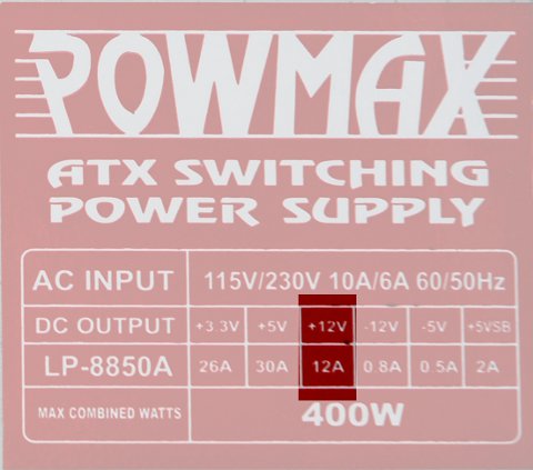
There are a few people that are looking to use this as their bench supply for a radio with an old ATX power supply laying in a closet some where. The board can take up to 25A through the PowerPole connectors. Below are the labels from two old ATX power supplies to show you where the current limits are listed.
I hope that this does the trick for y’all. We had a few extra PCBs left from this project. Post a comment if you would like to buy any of the extras.



RE the Emergency ATX 12 Volt power supply board: I may be interested in purchasing a board or two. Please email the details to <removed to prevent spam>@gmail.com
Regards,
kevin