ATX Power Supply Breakout Board
How many of you have or know of someone who has an old computer just sitting in the closet gathering dust. How many of you would like to have a multiple output bench power supply? Do you need an extra +12V DC power supply for your CB, ham shack or office? What we have here is a 4″ x 6.3″ PCB that has all the standard connectors needed to take the output connectors from an ATX power supply and give you easy access to them.
First up, a little bit of trivia for you. What is an often overlooked but sizable cost to any design? Connectors! This board has a lot of them. That’s OK because you don’t need a lot of them for it to be useful. If you don’t need the extra +12V DC rails from two PCI-E power connectors, don’t put them in. Same for the +12V EPS power connector. Here’s a list of all the ATX outputs this board is designed to handle:
- 24-pin ATX v2.0 main power connector
- +12 VDC, +5 VDC, +3.3 VDC, -5 VDC and -12 VDC
- The -5 VDC may not be on some ATX v2.0 or greater power supplies, as it was taken out of the standard, but it is often included.
- The 20-pin ATX v1.0 can fit into the 24-pin connector. What you loose is some of the current capacity on the +3.3 VDC rail.
- Molex pheripheral connector
- +12 VDC and +5 VDC
- This is on the same rail as the main power connector
- 8-pin ATX EPS connector
- +12 VDC
- This connector is often included on power supplies designed for multiple physical processors
- This is its own rail
- The 4-pin Axillary 12V connector will also fit in this socket.
- 8-pin PCI-Express power connector(x2)
- +12 VDC
- This will also fit the 6-pin versions
- This is its own rail
Like I said, it has a lot of connectors, and those are just the input connectors. Now for the output connectors:
- +12 VDC – All of these have both 25A Anderson Powerpole connectors and terminal blocks
- +5 VDC – This guy gets a lot of connectors. He has the Powerpoles, terminal block and USB ports with places for the resistors necessary for the different charging standards. See my prior post about USB charging.
- +3.3 VDC, -5 VDC & -12 VDC – Terminal blocks only
- Control lines – these lines are brought out to a standard header that you can measure or set them with.
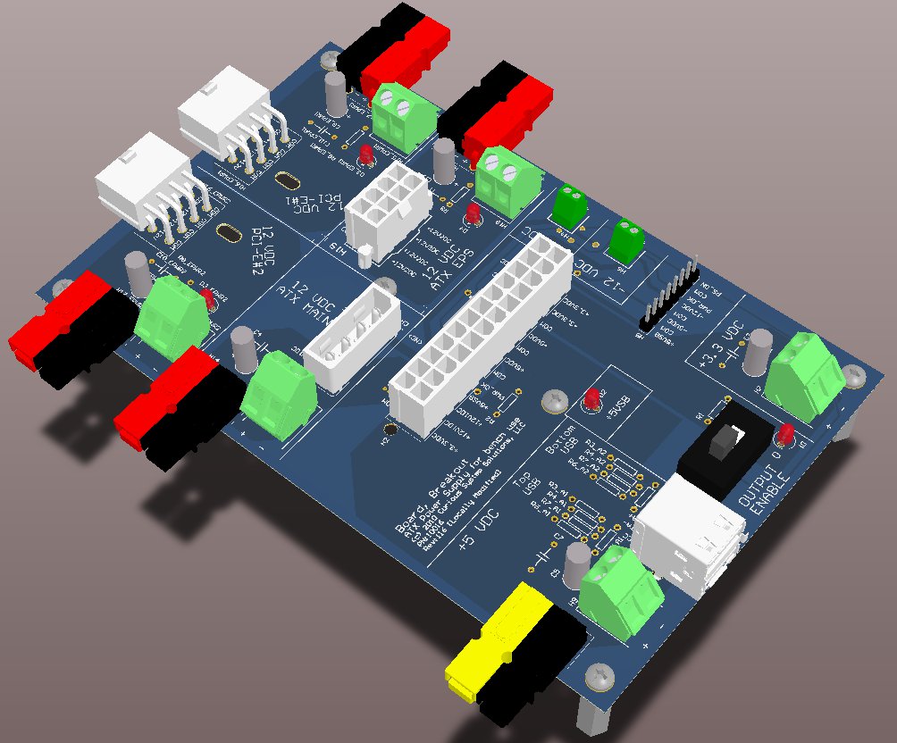
So, what does all this look like you ask? Here you are:
A few niceties were added to the board to make it a little more user friendly. Each of the additional +12 VDC rails have space for an LED so that you can tell it is powered. There are holes for 4-40 threaded screws and standoffs so that the board is supported and you are not trying to short your connectors with whatever surface you are setting it on. There is also space for an on/off switch to control the PS. For those of you interested in building this yourself, here are some brief instructions:
- Get the Gerber Files and have the board fabricated on 0.062″ thick FR-4 (the standard stuff). The board is designed such that most places that do prototype boards will take it. If you can get 2 0z. copper layers, that’s good. 1 oz. copper is OK.
- Buy the components. These can be purchased from Mouser or Newark. Don’t forget to buy extra Powerpoles if you decide to use them. You can often get packs of the housings and contacts together. Just get the 30 A or 15 A contacts for your cables. The 45 A contacts are a real pain if you don’t buy the crimper for them. I’ve wasted an hour before trying to solder one of the 45A contacts onto a cable in such a way as it would fit into the housing.
- Solder and enjoy. Make sure to get the schematics so you know what goes where, and which resistors got to what pins for the USB ports.
I hope that you find this a good way to put your old power supplies to use, or to test ones you might think are bad. Here’s a few pictures of the fabricated board.

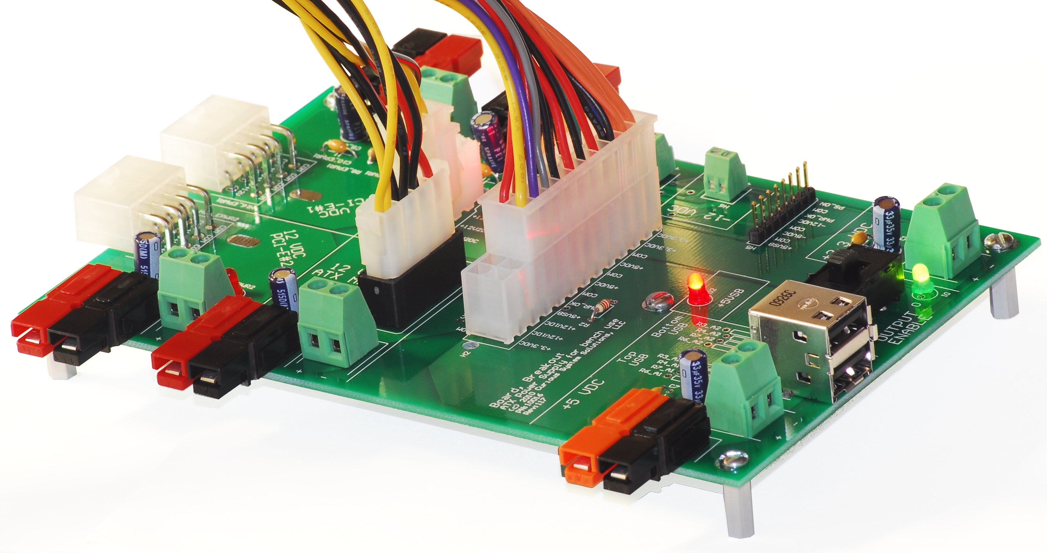
Fabricated breakout board with +5VSB (Standby) light and power light on

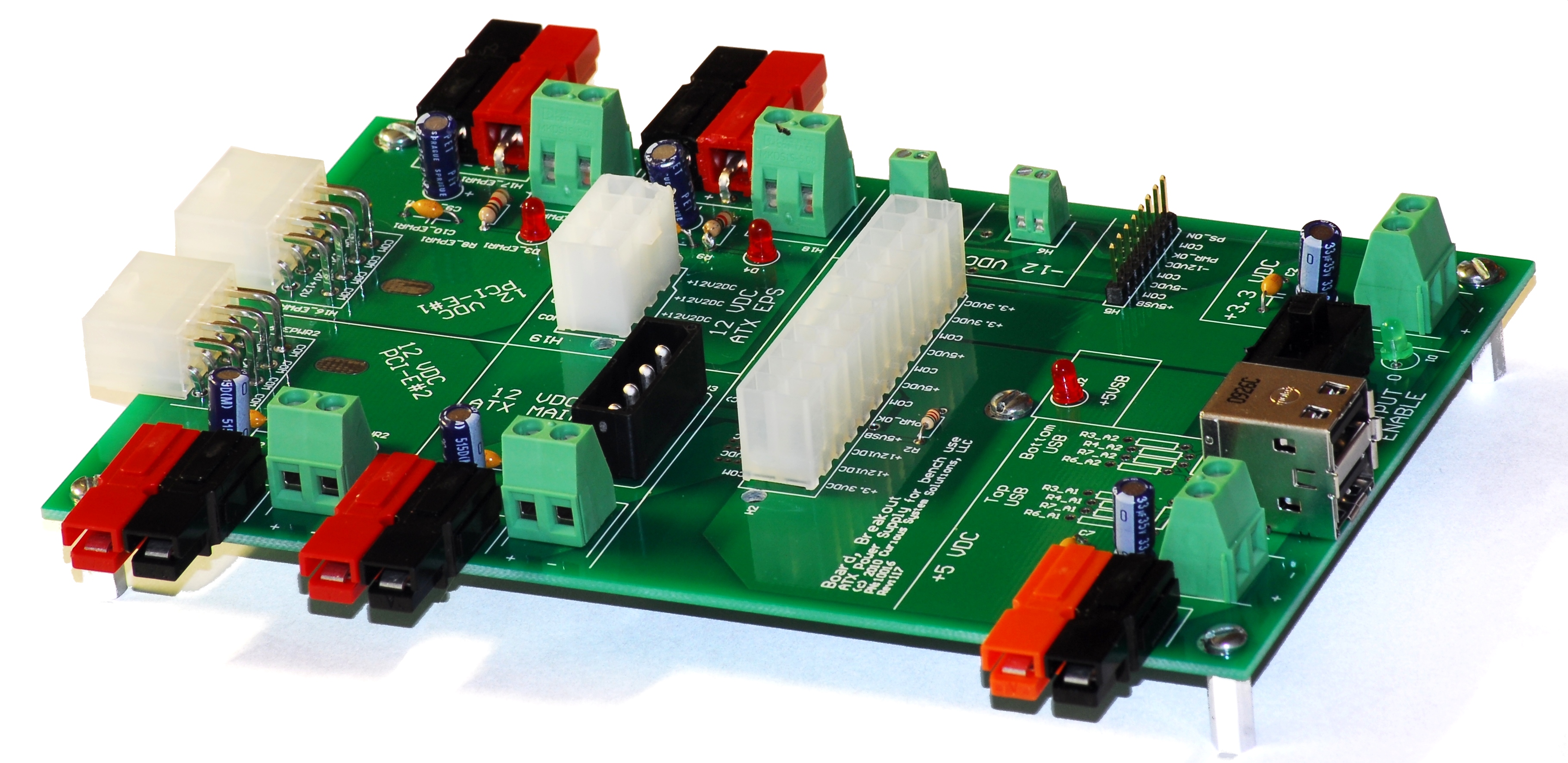
Fabricated board without cables attached
For more of the details behind this, I’ll be making a more detailed post in the future.
Appendix: Bill of Materials
| P/N: 10016 | |||||
| Description | Designator | Manufacturer | P/N | Qty. | Value |
| Aluminum Electrolytic Capacitor | C1, C3, C5, C9_EPWR1, C9_EPWR2, C11 | Vishay/Sprague | 515D336M035JA6AE3 | 6 | 33 uF |
| Capacitor | C2, C4, C7, C10_EPWR1, C10_EPWR2, C12 | TDK | C1608X7R1E104K | 6 | 0.1 uF |
| ATX v2.0 Motherboard Header | H2 | Molex | 442060007 | 1 | |
| ATX Peripheral Power Connector | H3 | Molex | 15244742 | 1 | |
| Terminal Block | H4, H6 | Phoenix Contact | 1725656 | 2 | |
| Terminal Block | H7, H9, H13, H15_EPWR1, H15_EPWR2, H18 | Phoenix Contact | 1733570 | 6 | |
| Header, 8-pin | H5 | Molex | 457180003 | 1 | |
| USB Header, Dual, Stacked | H12 | FCI | 72309-8034BLF | 1 | |
| PCI-E 8-Pin Power Header | H16_EPWR1, H16_EPWR2 | AMP | 1586041-8 | 2 | |
| ATX 12V EPS Header | H19 | Molex | 39-28-1083 | 1 | |
| Mechanical Screw | M1, M3, M4, M5, M6, M7 | Keystone | 30M0258 | 6 | |
| Mechanical Standoff | M2, M8, M9, M10, M11, M12 | Keystone | 1893 | 6 | |
| SPST Switch | S1 | C&K Components | L101011MS02Q | 1 | |
| LED | D1, D2, D3_EPWR1, D3_EPWR2, D4 | Knightbright | WP132XID | 5 | |
| European Phone Charger Resistors | R5_A1, R5_A2 | Vishay/Dale | CCF55200RFKE36 | 2 | 200 |
| LED Resistors | R1 | KOA Speer | MF1/4DCT52R2800F | 1 | 280 |
| LED Resistors | R2,R8_EPWR1, R8_EPWR2, R9 | Vishay/Dale | CCF07510RJKE36 | 4 | 510 |
| Apple Low-current Charge Resistors | R3_A1, R3_A2 | Vishay/Dale | CCF5549K9FKE36 | 2 | 49.9k |
| Apple High-current Charge Resistors | R3_A1, R3_A2 | KOA Speer | MF1/4DC4302F | 2 | 43k |
| Apple Charge Resistors | R6_A1, R6_A2 | Vishay/Dale | CCF5575K0FKE36 | 2 | 75k |
| Apple Charge Resistors | R4_A1, R4_A2, R7_A1, R7_A2 | Vishay/Dale | CCF5549K9FKE36 | 4 | 49.9k |
| 2×1 Powerpole Assembly | H11,H14, H17_EPWR1, H17_EPWR2, H20 | Anderson Power Products | 1377G12 | 10 | Contacts |
| 2×1 Powerpole Assembly | H11,H14, H17_EPWR1, H17_EPWR2, H20 | Anderson Power Products | 1327G6 | 5 | Black Housing |
| 2×1 Powerpole Assembly | H14, H17_EPWR1, H17_EPWR2, H20 | Anderson Power Products | 1327 | 4 | Red Housing |
| 2×1 Powerpole Assembly | H11 | Anderson Power Products | 1327G17 | 1 | Orange Housing |
-
[…] sucks when you need 12 VDC and your power supply just died. Previously we made an ATX breakout board to turn an ATX power supply into a fixed voltage bench DC power supply. Here we present a board […]
[…] sucks when you need 12 VDC and your power supply just died. Previously we made an ATX breakout board to turn an ATX power supply into a fixed voltage bench DC power supply. Here we present a board […]
Leave a Comment


Hi, are the Gerber files available? (there is nothing linked to the tag).
Excellent work btw 🙂
Thanks. The link to the gerbers has been fixed. It is http://blog.curioussystem.com/wp-content/uploads/2010/10/ATX-Breakout-Board-v2.zip
altium is still relatively new to me, so I’ll have to ask where you found the ATX v2.0 Motherboard Header and stuff like that
If you’re talking about the 3D model, http://www.tracepartsonline.net and http://www.3dcontentcentral.com are two great resources. Many vendors now allow you to download STEP models of their parts. After you have the pad layout correct in Altium, just import the model and position it to match your pads.
One word of caution about the ATX MB headers, the way the pins are designed makes it hard to tell which way the connector pins out in the ATX spec. I know my layout works (and the reverse does not) so you can look at the labeling in the figures to make sure you have yours correct.
Hello Chad,
Would it be possible to have a copy of the circuit diagram?
Regards,
Andrew
Odd… Most people who build ATX to power/bench supply converters put a load on the 5 volt rail, but none of yours seem to do that.
A popular choice is a 12v. auto bulb. The reduced voltage means it should last for a long while on the 5 v. rail.
Any chance you could supply the Altium libraries you used for the headers (or a link to where you found them)?
Hello Chad. Is it possible to get your Altium PCB / SCH / Library files for this board? Thanks for the consideration.